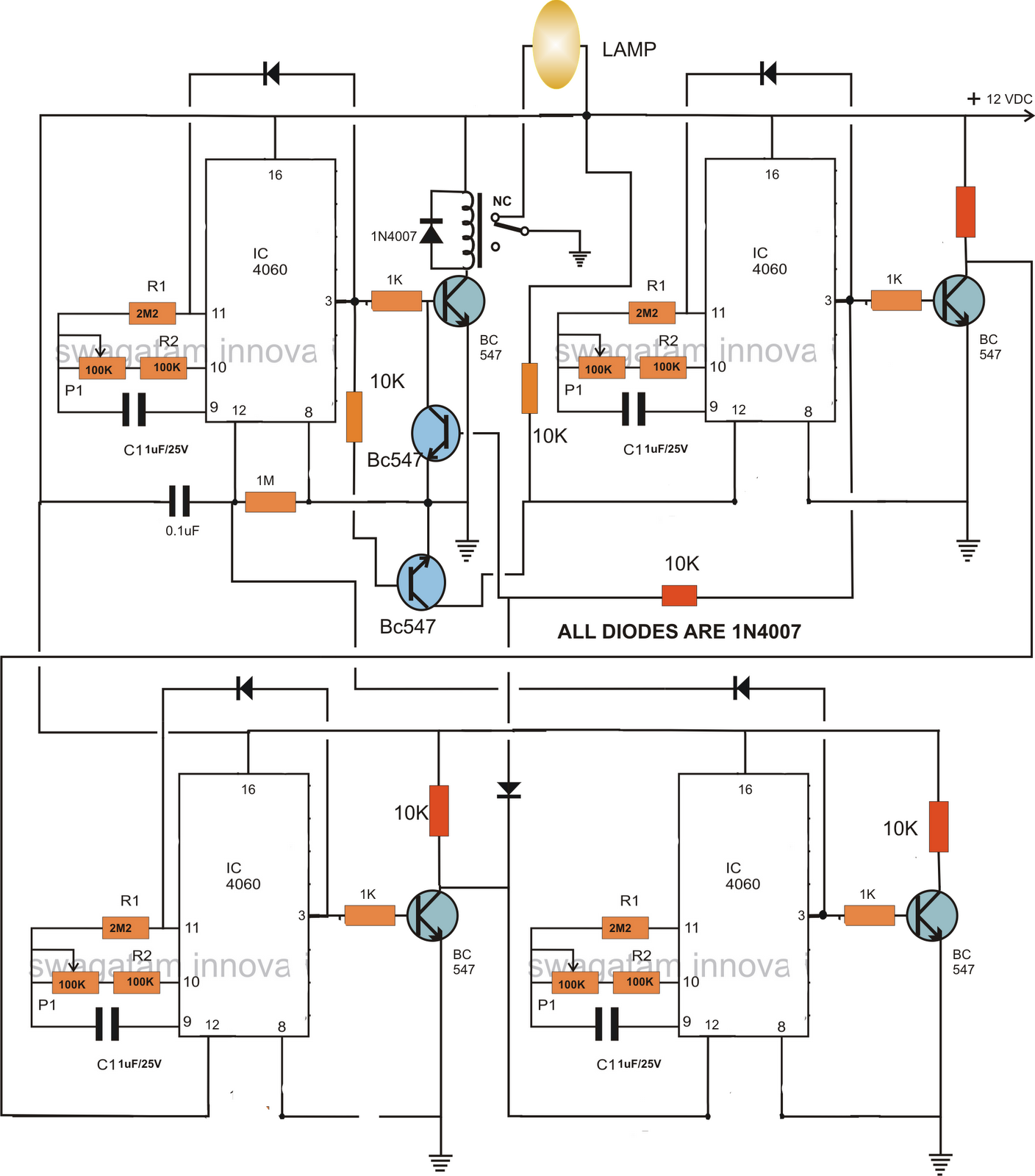
[diagram] electrical timer diagram Simple delay timer circuits explained Dancing light using 555 timer
Electrical circuit diagram cycled on and off timer under Timer Circuits
Timer delay eleccircuit circuits relay transistor Timer circuit diagram minute delay wiring time relay 555 using monostable 15 circuits ic electronics circuitdigest simple 55 seconds electronic How to read electrical schematics
Timer 555 circuit diagram
Electrical timer circuit diagram555 timer circuit using light dancing circuits diagram easyeda chip pcb pulse 555timer ne555 projects electronics time astable lm555 mode Electrical circuit diagram cycled on and off timer under timer circuitsElectrical timer wiring diagram.
Adjustable timer circuits using ic 555Led chaser using 4017 counter and 555 timer Adjustable timer circuit using 5554017 ve 555 entegreli ayarlanabilir 10'lu led yürüyen işık devresi ve.

How does ne555 timer circuit works
Timer 555 circuit diagram schematic ne555 datasheet discrete kit pinout block does circuits transistor works eleccircuit integrated functional pins connectionTimer circuit diagram free download Timer circuit diagram filter sand slow symbol schematic power volt water supply operation spells dry duringTypes of timer circuits with schematics and its working principle (2023).
Timer circuit delay time eleccircuit circuits electronic relay transistor rcElectronic timer circuit 16 hours adjustable timer circuit diagramSimple long duration timer.

Simple long duration timer
Timer circuits using 555 icSlow sand filter operation during dry spells A simple timer circuit diagram with ic 555Circuit timer diagram electrical off cycled circuits full gr next counter above size click.
Delay timer circuits circuit simple electronic explained diagram homemade projects schematics step two electronics seconds sequential fewDelay timer circuits circuit simple electronic explained diagram projects homemade trigger electronics step seconds two schematics few sequential long active Timer simple op amp long duration circuit using rectifier circuits wave full eleccircuit icTimer circuit diagram.

Simple delay timer circuits explained
Circuit timer circuits using simple 555 ic diagram make switch buzzer adjustable delay minutes button ic555 connect please push bourgeoisie1 minute timer circuit diagram Simple delay timer circuits explained – homemade circuit projectsSimple delay timer circuits explained homemade circuit, 54% off.
[diagram] basic electrical timer wiring diagramsSimple long duration timer Wiring in a relayDiagram 4017 555 led chaser capacitor timer wiring using counter circuit motor run start ic phase.

Electrical timer circuit diagram
555 timer schematics temporizador diagrama astable devresi ne555 monostable circuits microcontroller voltage trigger diagrams colores pinesDelay circuits circuit timer relay electronic sequence arduino sirkuit sequential alarm transistors pressed schematics Digital timer circuit diagram.
.

Adjustable Timer Circuit using 555

LED Chaser using 4017 Counter and 555 Timer

How to Read Electrical Schematics - Circuit Basics

Electrical circuit diagram cycled on and off timer under Timer Circuits

Adjustable Timer Circuits Using IC 555

electrical timer wiring diagram | Timer, Circuit diagram, Electricity
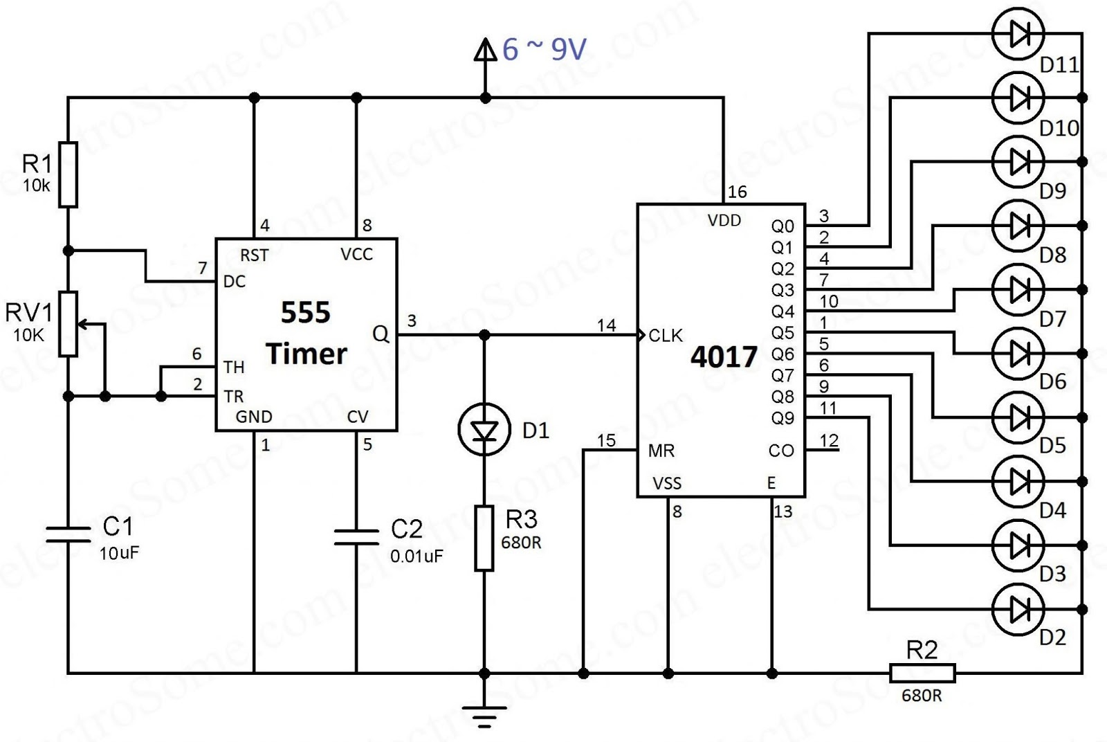
4017 ve 555 Entegreli Ayarlanabilir 10'lu LED Yürüyen Işık Devresi ve
